Setting up code libraries for use with Line of Balance graphs
Before you can generate a Line of Balance graph, you must set up two code libraries - one to represent the location breakdown structure and another to represent the stages within your unit networks - then assign codes from these libraries to the bars and tasks that you want to include in the Line of Balance graph.
Setting up a 'location' code library
You must set up a 'location' code library to represent the location breakdown structure for which you want to generate a Line of Balance graph. Each code in the 'location' code library represents a different location: if you model unit networks as multi-task bars, each code represents an individual bar; if you model unit networks as summary groups, each code represents an individual summary task.
The 'location' code library can be a flat list, or hierarchical. For example:
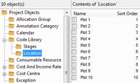
- If you were planning the construction of a housing estate, you could set up a non-hierarchical code library, with a code to represent each individual plot on the estate.
- If you were planning the renovation of an office block, you could set up a hierarchical code library, with a code to represent each room, divided into folders to represent the floors of the office block.
 Illustration
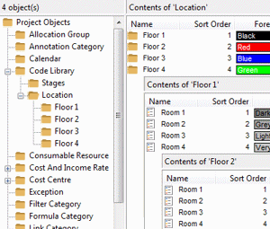
Note that the 'location' code library hierarchy can have as many levels as you like. For example, in the hierarchical code library illustrated above, you could create an additional level of folders to represent different zones on each floor.
Note that the code library that you create to represent your location breakdown structure can have any name: it does not have to be called 'Location'. Note also that the names of the codes within the library do not have to be identical to the names of the unit networks to which they will be assigned; although it does make sense to do this.
You define the order in which the individual locations - ie the individual units within each unit network - are expected to be achieved by assigning a numerical sort order to the codes within the 'location' code library. You can do this by entering the sort order in the Sort Order column in the Library Explorer list view, or by editing the properties of each code and entering the sort order in the Sort order field on the Code Library Entry Properties dialog. This sort order is used to calculate the number of units achieved in the Y axis of a Line of Balance graph.
In the non-hierarchical example above, the codes relating to each plot have been assigned a numerical sort order that indicates the order in which the plots are expected to be completed: Plot 1 is expected to be completed first, so this has been assigned a sort order of 1; Plot 2 is expected to be completed second, so this has been assigned a sort order of 2; and so on. The locations are therefore ordered sequentially from Plot 1 to Plot 10. When Plot 1 is complete, one unit has been achieved; when Plot 10 is complete, ten units have been achieved.
In the hierarchical example above, the codes relating to rooms in each folder have been assigned a numerical sort order that indicates the expected order of completion, as have the folders relating to each floor. With four floors, each floor comprising four rooms, there are sixteen rooms in all. The locations are therefore ordered sequentially from Floor 1.Room 1 to Floor 4.Room 4. When Floor 1.Room 4 is complete, four units have been achieved; Floor 2.Room 4 is complete, eight units have been achieved; when Floor 4.Room 4 is complete, sixteen units have been achieved.
Once you have set up your 'location' code library, you must assign the codes from the library to the individual bars or summary tasks that represent the different locations.
By default, each location as it appears on the Y axis of a Line of Balance graph is one unit in height. You can apply different heights to the location rows on the Y axis by creating an 'integer'-type user-defined field called LOB_ROW_HEIGHT for the code library entry table and entering a different value, between 1 and 100, into this field for each 'location' code.
To create the LOB_ROW_HEIGHT user-defined field:
- On the Project tab, in the Properties group, click User Field Manager. The User Field Manager dialog appears (the User Field Manager command is unavailable if the project contains any unsaved changes, if a Properties dialog is active, or if the project is stored on a server-mounted data source).
- Select Code Library Entry in the Object type field. If the LOB_ROW_HEIGHT field appears in the dialog, the user-defined field has already been created, so you can skip the following steps.
- Click Add. The Add User Field dialog appears.
- Select the Integer radio button.
- Enter LOB_ROW_HEIGHT in the User field name field.
- Click OK to confirm the dialog and create the new user-defined field.
- Click Close to apply the user-defined field and close the User Field Manager dialog. Any views onto the active project are closed so that the database can be updated.
Each code library entry is initially assigned a LOB_ROW_HEIGHT value of 0. If you leave any of the location codes with 0 in this field, they will be excluded from Line of Balance graphs, so you must edit each location code and enter a value between 1 and 100 into the LOB_ROW_HEIGHT field. If you add new code library entries to your 'location' code library, you must remember to enter values other than 0 into the LOB_ROW_HEIGHT field, or the new locations will be excluded from Line of Balance graphs.
To enter values into the LOB_ROW_HEIGHT user-defined field for your locations, either:
- Within Library Explorer, view your location code library and enter a number into the LOB_ROW_HEIGHT column that appears in the right pane of Library Explorer. If the LOB_ROW_HEIGHT column does not appear, you can display it in Library Explorer
- View the User Fields tab of the each code library entry's Properties dialog and enter a number into the LOB_ROW_HEIGHT field on the dialog.
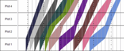
The following examples show the effect that different LOB_ROW_HEIGHT values would have on a set of four location rows.
In the following example, all location codes have been assigned a LOB_ROW_HEIGHT value of 1:

This results in all the location rows being the same height:
In the following example, the Plot 1 location code has been assigned a LOB_ROW_HEIGHT of 2; the other three location codes have been assigned a LOB_ROW_HEIGHT of 1:

This results in the Plot 1 location row being twice the height of the other three location rows, which are reduced in height proportionally so that the Line of Balance graph as a whole does not increase its height:
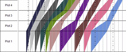
In the following example, the Plot 1 location code has been assigned a LOB_ROW_HEIGHT of 10; the other three location codes have been assigned a LOB_ROW_HEIGHT of 1:

This results in the Plot 1 location row being ten times the height of the other three location rows:
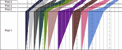
In the following example, the Plot 2 location code has been assigned a LOB_ROW_HEIGHT of 0; the other three location codes have been assigned a LOB_ROW_HEIGHT of 1:

This results in the Plot 2 location row being excluded from the Line of Balance graph altogether:
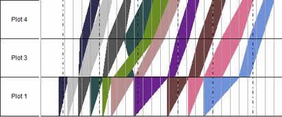
Setting up a 'stages' code library
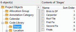
You must set up a 'stages' code library to represent the individual stages - or trades, or gangs - that make up each unit network. Each code in the 'stages' code library represents a different stage: if you model unit networks as multi-task bars, each code represents an individual task on a bar; if you model unit networks as summary groups, each code represents an individual bar within a summary group.
You must set up the 'stages' code library as a flat, non-hierarchical list.
Note that the code library that you create to represent your stages can have any name: it does not have to be called 'Stages'. Note also that the names of the codes within the library do not have to be identical to the names of the tasks or bars to which they will be assigned.
You define the drawing order of the individual stages in a Line of Balance by defining a numerical sort order to the codes within the 'stages' code library. Lines representing stages with a higher sort order are drawn on top of those representing stages with a lower sort order in cases of overlap in a Line of Balance graph. In the example above, the line representing the Carpenter stage would be drawn on top of the line representing the Brick to DP stage.
Once you have set up your 'stages' code library, you must assign the codes from the library to the individual activities within each unit network that represent the different stages.
Introduction to Line of Balance graphs
Modelling unit networks for use with Line of Balance graphs
Assigning Line of Balance codes to unit networks and individual activities
