Splitting 3D objects in a 3D model
You can split 3D objects in a 3D model into a number of smaller objects. This enables you to associate the smaller 3D objects with tasks in a project individually. 3D object splitting may be useful in the following circumstances:
- Where a 3D object represents more than one individual item. For example, you may want to split a 3D object that represents multiple columns, windows or beams into individual objects so that you can schedule them individually rather than as a single entity.
- Where a 3D object represents a single object that needs to be split into multiple objects for the purposes of scheduling. For example, you may want to split a 3D object that represents a single concrete slab into two individual objects if half of the slab needs to be laid on one day and the other half needs to be laid the next.
Once you have split a 3D object, it is possible to then split the resulting objects. You can carry on splitting in this way until you have split 3D objects into whatever level of detail you require for scheduling.
There are three methods of splitting 3D objects:
- Manually, by clicking and dragging to define the lines along which to cut. This is a good way to split 3D objects if you want to split a single object in a complex way, or if you want to specify the line(s) of the cut visually. You cannot split multiple 3D objects manually at the same time.
- Splitting 3D objects where they intersect with one or more other objects. This is a good way to split 3D objects if you want to split one or more objects that overlap incorrectly with other objects, or if you want to split objects based on their physical location. For example, you may want to split a series of columns at each floor of a building; or you may want to split the vertical bars in a multi-paned window where they meet the horizontal bars.
- Splitting 3D objects along a particular axis. This is a good way to split 3D objects if you want to split one or more objects evenly according to a specified number of cuts, or with cuts positioned at specific percentages along an axis. You can split multiple 3D objects in this way at the same time.
You cannot split site objects.
To split a 3D object manually by clicking and dragging:
- Display the 3D model in orthogonal mode. You can split 3D objects manually in perspective mode, but it is easier to do it in orthogonal mode.
- Right-click the 3D object that you want to split in the IFC Model pane and select Split/Merge Products - Split Product Manually from the menu that appears. The Split Product Manually dialog appears.
- When the dialog appears, all 3D objects in the 3D model apart from the one selected is hidden automatically, to make it easier for you to define the split. If you want to redisplay the 3D objects that are hidden, clear the Only show products being split check box.
- Click the surface of the 3D object that you want to split. The 3D object is realigned in the IFC Model pane so that the selected surface faces you directly. A line is displayed on the surface, with two positioning points:
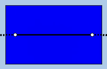
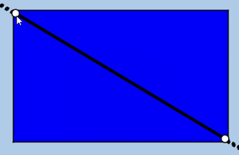
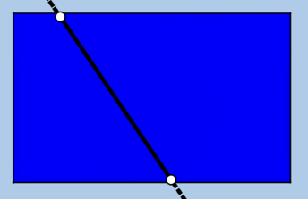
- Initially, the line is positioned directly across the middle of the selected surface. Click and drag the positioning points as required to move the line across the surface, as illustrated below:
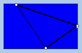
- For a more complex split, you can add new positioning points. To do this, left-click the line. A new point appears, which you can click and drag to the required position:
- Rotate the 3D object in the IFC Model pane to check that the split is going to be applied correctly with respect to all surfaces of the selected object; adjust or add new positioning points as required:
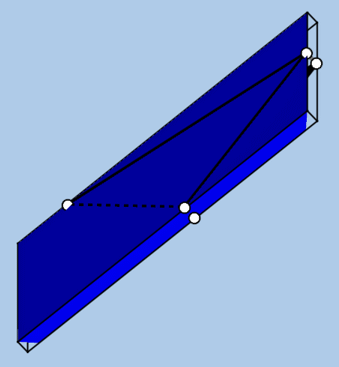
- By default, the Complete split shape check box is selected, ensuring that the split lines form a closed shape. If you clear this check box, the split lines form an open shape:
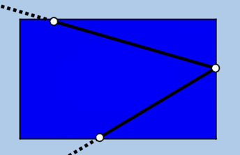
- You can use the Align on Camera and Align on Surface buttons to determine the way in which the split lines are aligned: click Align on Camera to adjust the split lines to align with the current camera position, which can help you to split 3D objects at odd angles; click Align on Surface to adjust the split lines to align with the selected surface.
- Select the Set build order on split products check box if you want a numeric build order to be assigned to each of the 3D objects that are created as a result of the split, starting with the number that you enter in the Starting from field.
- If you are redoing a split because the build orders were initially assigned to the resulting 3D objects in the wrong order, select the Reverse build order assignment check box to reverse the order in which the build orders are assigned to the resulting 3D objects.
- If you are happy with the results of the split, click OK to close the dialog and split the selected 3D object as specified. All properties of the original 3D object except the internal identifier are copied to the resulting objects.
If the original 3D object was included in one or more IFC product searches, the resulting objects are included in the IFC product searches automatically. However, if the original 3D object was included in one or more IFC product selections, the resulting objects are not included in the IFC product selections automatically, and the Update IFC Product Selections dialog appears, listing the IFC product selections in which the original 3D object was included. - To update an IFC product selection so that it includes the resulting 3D objects rather than the original object, select the check box to the left of the IFC product selection and click Update. Updating IFC product selections in this way means that any tasks that were associated with the original 3D object via an IFC product selection will be associated with the resulting objects. If you choose not to update any IFC product selections, you will need to associate the resulting 3D objects with tasks manually.
There are three methods of splitting a 3D object where it intersects with one or more other objects:
- Splitting where the 3D object intersects with any spaces or storeys that are defined in the 3D model. This is a good way to split 3D objects if, for example, you want to split a single column at each floor of a building.
- Splitting where the 3D object intersects with any objects that are grouped together by a particular IFC product search or IFC product selection. This is a good way to split 3D objects if, for example, you want to split a single beam that is intersected by a series of perpendicular beams that have been grouped together by an IFC product search or IFC product selection.
- Splitting where the 3D object intersects with one or more objects that you select in the 3D model. This is a good way to split 3D objects if, for example, you want to split a single beam that is intersected by a series of perpendicular beams that have not been grouped together in any way.
To split a 3D object where it intersects with one or more other objects:
- Right-click the 3D object that you want to split in the IFC Model pane and select Split/Merge Products - Split Products by Other Products from the menu that appears. The Split By Products dialog appears. You can split more than one 3D object at the same time by selecting the objects first then right-clicking one of them and selecting Split/Merge Products - Split Products by Other Products, but you should do this only if all of the objects are to be split in the same way.
- The dialog indicates the number of 3D objects that were selected for splitting. All 3D objects in the 3D model remain displayed. If you want to display temporarily only those 3D objects that are going to be split, click and hold down the Show button. Release the button to redisplay all 3D objects in the 3D model.
- Specify the way in which to split the selected 3D object:
- To split the selected 3D object where it intersects with any spaces or storeys that are defined in the 3D model, click the Spaces/Storey radio button. If the spaces in the 3D model are not obvious to see, click and hold down the Show Spaces button to display them temporarily. Release the button to redisplay all 3D objects in the 3D model. If no spaces are defined in the 3D model, the Spaces/Storey radio button is unavailable.
- To split the selected 3D object where it intersects with any objects that are grouped together by a particular IFC product search or IFC product selection, click the IFC product search/selection radio button then select an IFC product search or IFC product selection in the field below. If you want to display temporarily only those 3D objects that are grouped by the selected IFC product search or IFC product selection, click and hold down the Show button. Release the button to redisplay all 3D objects in the 3D model.
- To split the selected 3D object where it intersects with one or more objects that are not grouped together in any way, click the Other product(s) radio button, CTRL-click the objects in the 3D model at which you want the splits to be made then click Select. The dialog indicates the number of 3D objects that you have selected. If you want to display temporarily only those 3D objects that you have selected, click and hold down the Show button. Release the button to redisplay all 3D objects in the 3D model.
- Use the Split at intersection group of fields to specify the precise point at which the splits should be created at each intersection. It is useful to be able to specify this if you are creating splits at intersections with spaces - or at intersections with products such as thick floors. In the latter example, this enables you to choose whether to create splits at the ceiling, the floor, or in the middle of the two:
- To split the selected 3D object at the start of each intersection, click the Start radio button.
- To split the selected 3D object in the middle of each intersection, click the Middle radio button.
- To split the selected 3D object at the end of each intersection, click the End radio button.
These three options are illustrated below: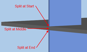
What constitutes the "start" or "end" of an intersection varies, depending on the 3D objects that you have selected. If you split a 3D object at what you think of as the "start" of an intersection, only to discover that the split has been created at what you think of as the "end", remove the split and recreate it, this time choosing to create the split at the "end". The middle, of course, does not vary. - Select the Set build order on split products check box if you want a numeric build order to be assigned to each of the 3D objects that are created as a result of the split, starting with the number that you enter in the Starting from field. If you assign a build order to split 3D objects, it is used to determine the order in which split 3D objects appear during timeline simulations in cases where more than one object is assigned to a single task. You can also use the build order as a criterion when creating IFC product searches, to specify which 3D objects should be included in an IFC product search. You can view the build order of 3D objects in the IFC Properties pane; note that the build order of non-split 3D objects defaults to 0.
- If you are redoing a split because the build orders were initially assigned to the resulting 3D objects in the wrong order, select the Reverse build order assignment check box to reverse the order in which the build orders are assigned to the resulting 3D objects.
- If you are happy with the results of the split, click OK to close the dialog and split the selected 3D object as specified. All properties of the original 3D object except the internal identifier are copied to the resulting objects.
If the original 3D object was included in one or more IFC product searches, the resulting objects are included in the IFC product searches automatically. However, if the original 3D object was included in one or more IFC product selections, the resulting objects are not included in the IFC product selections automatically, and the Update IFC Product Selections dialog appears, listing the IFC product selections in which the original object was included. - To update an IFC product selection so that it includes the resulting 3D objects rather than the original object, select the check box to the left of the IFC product selection and click Update. Updating IFC product selections in this way means that any tasks that were associated with the original 3D object via an IFC product selection will be associated with the resulting objects. If you choose not to update any IFC product selections, you will need to associate the resulting 3D objects with tasks manually.
To split a 3D object along a particular axis:
- Right-click the 3D object that you want to split in the IFC Model pane and select Split/Merge Products - Split Products from the menu that appears. The Split Product dialog appears. You can split more than one 3D object at the same time by selecting the objects first then right-clicking one of them and selecting Split/Merge Products - Split Products, but you should do this only if all of the objects are to be split in the same way.
- When the dialog appears, all 3D objects in the 3D model apart from those selected are hidden automatically, to make it easier for you to see the results of the split. If you want to redisplay the 3D objects that are hidden, clear the Only show products being split check box.
- Specify whether to split the 3D object according to the product axis or the world axis by clicking the appropriate Split using radio button.
 Illustration of the different axes
In the illustration of a 3D model below, the world axes are displayed:
- The X axis (blue) goes from the left of the 3D model to the right as it is currently displayed.
- The Z axis (green) goes from the top of the 3D model to the bottom as it is currently displayed.
- The Y axis (red) goes from the ground floor of the 3D model to the top floor.
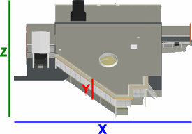
The relationship between the X and Z world axes and the building depicted in the 3D model changes depending on your viewpoint over the 3D model, but the relationship between the Y axis and the building does not change.
It is not possible to display product axes against an illustration of a complete 3D model, as product axes apply to individual 3D objects within a model, which means that two geographically close objects in a model can have completely different product axes. For this reason, we can only display product axes in relation to an individual 3D object in a 3D model. In the illustration of a 3D model below, the ledge along the top of the front of the building is selected and highlighted in orange and the product axes of this selected 3D object are displayed:
- The X axis (blue) goes along the length of the 3D object.
- The Z axis (green) goes along the breadth of the 3D object.
- The Y axis (red) goes from the lowest point of the selected 3D object to the highest point.
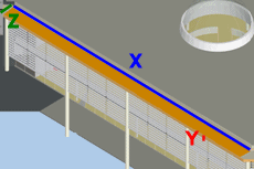
Unlike the world axes, the relationship between all of the product axes and the 3D object remains the same, regardless of your viewpoint over the 3D model.
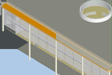
Before splitting a 3D object, you must consider which of the axes - world or product - would be the most appropriate to use. In this example - the ledge along the top of the front of the building - the result of splitting the 3D object in half along the X world axis is illustrated below:
The result of splitting the 3D object in half along the X product axis is illustrated below:
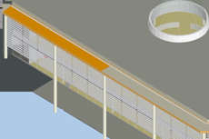
It is clear from the above illustrations that splitting the ledge according to the world axes would give undesirable results in this case: the ledge would be split at an odd angle. In this case, splitting the ledge according to the product axes would give the desired results.
- Specify whether to split the 3D object in one direction or in two directions by clicking the appropriate Split in radio button.
- For each direction, specify the axis along which you want to split the 3D object in the Axis fields.
- For each direction, specify the number of cuts that you want to make along the specified axis in the Number of cuts fields.
 Illustrations of splitting in one or two directions along various axes with differing numbers of cuts
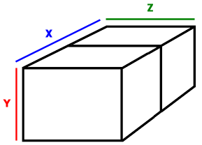
The illustrations below take the following 3D object as a starting point:
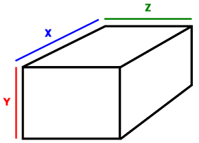
Splitting the 3D object along the X axis only with one cut would result in the following:
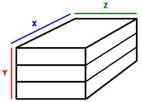
Splitting the 3D object along the Y axis only with two cuts would result in the following:
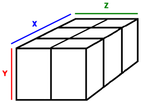
Splitting the 3D object along the Z axis with one cut and along the X axis with two cuts would result in the following:
- Click the Equal cuts radio button to split the 3D object evenly according to the specified number of cuts, or click the Specific fractions radio button to split the object with cuts positioned at specific percentages along the appropriate axis - you specify the percentages in the Cut at % fields below these radio buttons.
 Illustrations of splitting at specific percentage points along an axis
The illustrations below take the following object as a starting point - note that the object is illustrated in two dimensions only, for clarity:
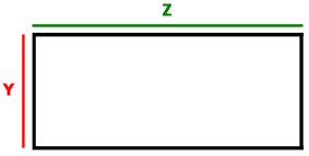
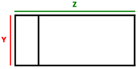
Splitting the object along the Z axis only with one cut at the 20% point would result in the following:
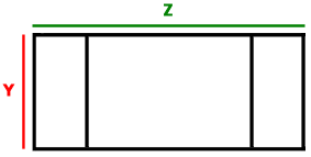
Splitting the object along the Z axis only with cuts at the 20% and 80% points would result in the following:
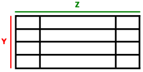
Splitting the object along the Z axis with cuts at the 20% and 80% points and along the Y axis with cuts at the 25%, 50% and 75% points would result in the following:
- Select the Set build order on split products check box if you want a numeric build order to be assigned to each of the 3D objects that are created as a result of the split, starting with the number that you enter in the Starting from field. If you assign a build order to split 3D objects, it is used to determine the order in which split 3D objects appear during timeline simulations in cases where more than one object is assigned to a single task. You can also use the build order as a criterion when creating IFC product searches, to specify which 3D objects should be included in an IFC product search. You can view the build order of 3D objects in the IFC Properties pane; note that the build order of non-split 3D objects defaults to 0.
- If you are redoing a split because the build orders were initially assigned to the resulting 3D objects in the wrong order, select the Reverse build order assignment check box to reverse the order in which the build orders are assigned to the resulting 3D objects.
- Click Preview to see the results of the split in the 3D model. Alternate split 3D objects are highlighted to accentuate the results of the split.
- If you are happy with the results of the split, click OK to close the dialog and split the selected 3D object as specified. All properties of the original 3D object except the internal identifier are copied to the resulting objects.
If the original 3D object was included in one or more IFC product searches, the resulting objects are included in the IFC product searches automatically. However, if the original 3D object was included in one or more IFC product selections, the resulting objects are not included in the IFC product selections automatically, and the Update IFC Product Selections dialog appears, listing the IFC product selections in which the original 3D object was included. - To update an IFC product selection so that it includes the resulting 3D objects rather than the original object, select the check box to the left of the IFC product selection and click Update. Updating IFC product selections in this way means that any tasks that were associated with the original 3D object via an IFC product selection will be associated with the resulting objects. If you choose not to update any IFC product selections, you will need to associate the resulting 3D objects with tasks manually.
If you want to undo a split or a merge, it is best not to use Asta Powerproject's standard Undo Ribbon command, but to use the Split/Merge Products - Remove Split right-click command to recombine split 3D objects, or the Split/Merge Products - Remove Product Merge right-click command to reseparate merged 3D objects. The reason for this is that if carrying out a split or a merge resulted in the need for one or more IFC product selections to be updated, you would need to click Undo twice: once to undo the IFC product selection updates and a second time to undo the split or merge itself. Using the Split/Merge Products - Remove Split and Split/Merge Products - Remove Product Merge right-click commands instead of Undo enables you to specify the way in which any IFC product selections are updated.
Specifying the build order of split 3D objects
Recombining previously-split 3D objects in a 3D model
Merging 3D objects in a 3D model
Reseparating previously-merged 3D objects in a 3D model
Copying split and merge data to a different revision of a 3D model