Positioning and resizing site objects
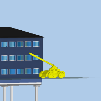
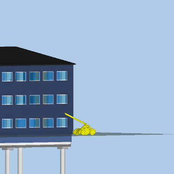
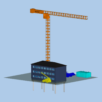
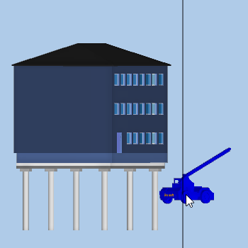
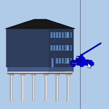
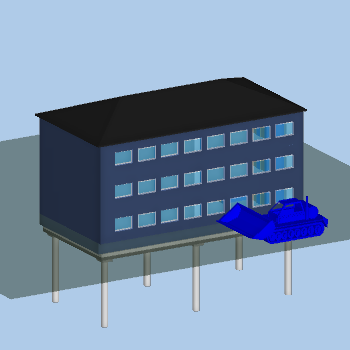
When you first add a site object to a 3D model, it is unlikely to appear exactly where you want it. Site objects are inserted at coordinate 0, 0, 0. If you cannot see a site object that you have just added to a 3D model, it may have appeared behind, or in the middle of, a building, so you may need to search for it. You will probably need to reposition and resize each site object so that it appears in the correct location and at the correct scale with respect to a 3D model, and to avoid situations like the following, in which a 'tanker' site object is displayed at a totally inappropriate scale, and in a position where it bisects the 3D model:
To position and resize a site object:
- Display the IFC group model of which the site object is a part in the IFC Model pane.
- On the 4D tab, in the Model group, click Model Properties. The IFC Group Model Properties dialog appears.
- Click the Site Objects tab.
- Select the site object that you want to position in the grid on the tab and click Set Position. The Site Object Positioning dialog appears.
- Click Centre in Viewer to adjust the display in the IFC Model pane so that the selected site object appears in the centre of the pane - this may make it easier to position the site object.
- Adjust the size and position of the site object as required - see the following sections for details of how to do this.
- Once the site object is positioned and sized correctly, click OK to close the Site Object Positioning dialog.
Use the Scale field on the Site Object Positioning dialog to specify an appropriate size for the selected site object.
In the following illustration, a site object is displayed at its normal scale - 100%:
In the following illustration, the site object is displayed at a scale of 50% - it appears half its normal size:
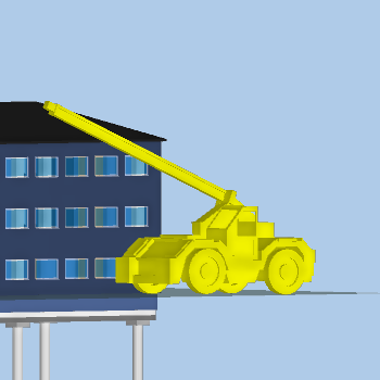
In the following illustration, the site object is displayed at a scale of 200% - it appears double its normal size:
Use the Visibility radio buttons to specify how to display objects in the IFC Model pane while positioning the selected site object. Experiment with the different options to find which one enables you to locate and position site objects with most ease:
- Click Normal to view the 3D model and any site objects as they are normally displayed.
 Illustration
A 3D model and site objects displayed normally:
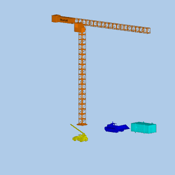
- Click Just site objects to hide the 3D model (or all 3D models, if more than one is included in the IFC group model) and display only the site objects. This may be useful if you cannot locate a new site object, which may have appeared behind, or in the middle of, a building.Illustration
Just site objects displayed - the 3D model is hidden:
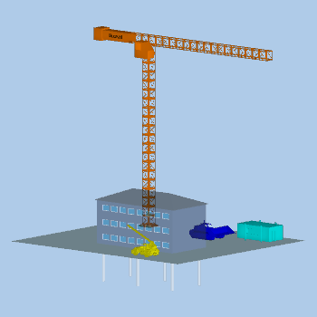
- Click Shade to display the 3D model (or 3D models) as partially-transparent and display the site objects as they are normally displayed. This may be useful when positioning site objects in relation to a building.Illustration
A 3D model displayed partially-transparent, and site objects displayed normally:
Use the Viewer mode radio buttons to specify how the mouse should work while you are positioning the selected site object. You will probably need to switch between the different options a number of times while positioning a site object to get it into the required position:
- Click Navigation to use the mouse to move around, rotate and zoom in and out, as normal. You may need to do this to position the 3D model in such a way that you can position the site object correctly in relation to it.
- Click Vertical to use the mouse to move the selected site object up or down vertically. After clicking this radio button, click and drag the selected site object to move it up and down vertically. A vertical line appears at the point at which you click, showing the vertical axis along which you can drag the site object. Moving a site object vertically is useful if it appears too high up, or too low down, in relation to the 3D model.It may help to view 3D models directly from the side when moving site objects vertically: viewing a 3D model at an oblique angle may make it more difficult to identify when a site object is at the desired vertical position.Illustration
In the following illustration, a site object is being moved up and down along the displayed vertical axis; the 3D model is viewed directly from the side to make the vertical movement more obvious:
- Click Horizontal to use the mouse to move the selected site object around the horizontal plane (essentially, forwards and backwards; left and right). After clicking this radio button, click and drag the selected site object to move it horizontally. Moving a site object horizontally is useful if it appears in the wrong location on the ground in relation to the 3D model. For example, you could move a site object horizontally to move it to a different location on the ground in front of a building, or from the front to the rear of a building.Depending on your viewpoint, it may appear that you are able to click and drag site objects in any direction when Horizontal is clicked. If you find this confusing, it may help to view the 3D model either directly from above, or directly from the side. Viewing a model in this way will make it easier to see that you are moving the site object in one plane only - forwards and backwards; left and right - and that you are not able to move it up and down.Illustration
In the following illustrations, a site object is being moved around the horizontal plane; the 3D model is viewed directly from above to make the horizontal movement more obvious:

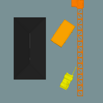
- Click Rotate to use the mouse to rotate the selected site object within the horizontal plane around a pivot point. After clicking this radio button, click and drag the selected site object to rotate it horizontally around a pivot point. Click and drag to the left to rotate the site object clockwise; click and drag to the right to rotate it anticlockwise. A vertical line appears at the point at which you click, showing the vertical axis around which you can rotate the site object. Rotating a site object is useful if it is oriented in the wrong direction. For example, you could rotate a 'site hut' site object to change the orientation of its long edge. The pivot point appears at the point at which you click in the IFC Model pane.It may help to view 3D models directly from above when rotating site objects: viewing a 3D model at an oblique angle may make it more difficult to identify when a site object is oriented correctly.Illustration
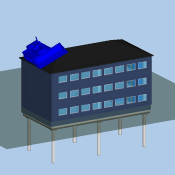
The following illustration shows a 'site hut' site object that is oriented incorrectly in relation to a 3D model; the 3D model is viewed directly from above to make the rotation more obvious:
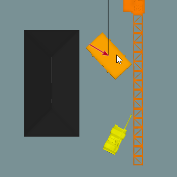
In the following illustration, the site hut is being rotated around a pivot point in the centre of the site object. This would happen if you clicked directly in the centre of the site object. The pivot point is highlighted in the illustration by a red arrow:
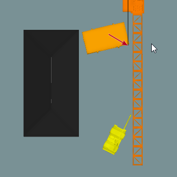
In the following illustration, the site hut is being rotated around a pivot point at one corner of the site object. This would happen if you clicked on a corner of the site object. The pivot point is highlighted in the illustration by a red arrow:
- Click Snap to surface to use the mouse to move the selected site object so that it sits on top of whichever surface you then click, oriented correctly according to the slope of the surface. After clicking this radio button, click the surface on which you want the selected site object to sit. For example, you could click the ground, or a sloping roof. The site object is moved instantly to sit on top of that surface, centred at the point at which you clicked. Snapping a site object is useful if it is not sitting correctly on a surface. This could be the case if the surface is sloped, or if you have moved, rotated or tilted the site object and want to revert it to a position at which it is sitting squarely on the ground.Illustration
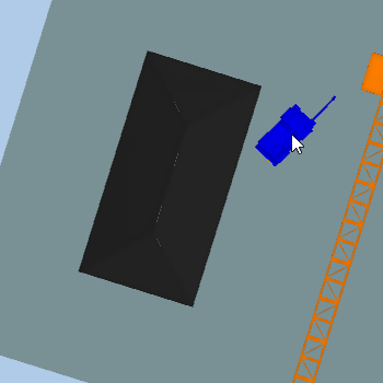
The following illustration shows a site object that is oriented incorrectly in relation to a 3D model:
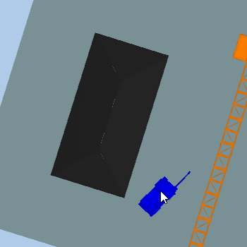
In the following illustration, the site object has been snapped to the ground surface in front of the 3D model:
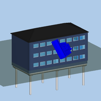
In the following illustration, the site object has been snapped to the sloping surface of a roof - obviously, this is not an appropriate place for a digger to be located, but it illustrates how site objects can be snapped to sloping surfaces:
- Click Tilt to use the mouse to move the selected site object into a sloping position. After clicking this radio button, click and drag the selected site object to tilt it up and down around a pivot point. Click and drag to the right to tilt the site object clockwise, making the left side of the site object higher than the right; click and drag to the left to tilt it anticlockwise, making the right side of the site object higher than the left. A vertical line appears at the point at which you click, showing the pivot point around which you can tilt the site object. Tilting a site object is useful if it is not sitting correctly on sloping ground, or on a sloping roof. For example, you could rotate a site object that is positioned on sloping ground to make it appear correctly in relation to the slope.It may help to view 3D models directly from the side when tilting site objects, with the sloping surface side-on to you: viewing a 3D model at any other angle may make it more difficult to identify when a site object is tilted correctly.Illustration
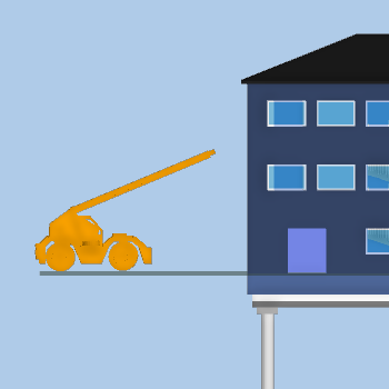
The following illustration shows a site object that has not been tilted; the 3D model is viewed directly from the side to make the tilting more obvious:
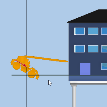
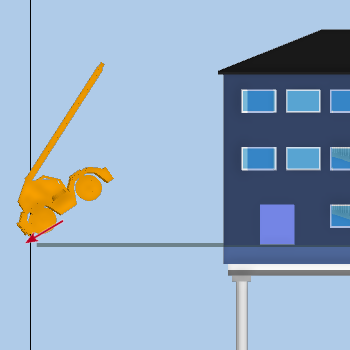
In the following illustration, the site object is being tilted around a pivot point in the centre of the site object. This would happen if you clicked directly in the centre of the site object. The pivot point is highlighted in the illustration by a red arrow:
In the following illustration, the site object is being tilted around a pivot point at the lower-left corner of the site object. This would happen if you clicked on a corner of the site object. The pivot point is highlighted in the illustration by a red arrow:
When moving a site object around the horizontal plane, you may find the Snap vertically check box useful. With this check box cleared, the selected site object is 'snapped' - ie restricted - to the horizontal plane on which it is currently positioned as you move it around. This plane could be the ground surrounding a building, or the level of a building's roof. With this check box selected, you are able to change the horizontal plane to which the site object snaps as you move it around, from ground level to roof, or vice-versa.
To change the horizontal plane to which the selected site object snaps:
- Select the Snap vertically check box and click the Horizontal radio button.
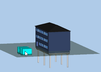
- Click and drag the selected site object around the horizontal plane of the ground until you come to a part of the 3D model that represents the building:
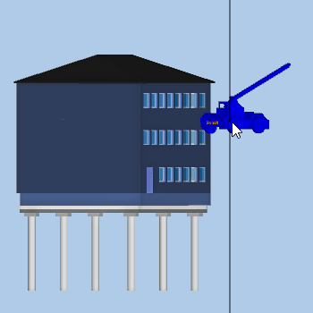
As you drag the mouse over the building, the selected site object 'jumps' from the ground to the roof. It is now snapped to the plane of the roof rather than to the plane of the ground outside the building: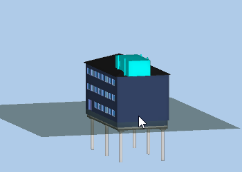
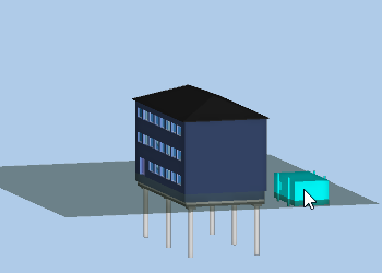
- Release the mouse button when the site object is positioned correctly on the roof. If you continue dragging the site object away from the building rather than releasing the mouse button, it will 'jump' back down from the roof to the ground:
You use two variations of the Site Object Positioning dialog to set the start and end points of site objects when defining actions to animate them. These dialogs - the Site Object Action - Set Start Position dialog and the Site Object Action - Set End Position dialog - differ from the Site Object Positioning dialog in that they do not include the Scale field, as you cannot change the size of site objects when setting start and end points.
Adding site objects to a 3D model
Animating site objects to reflect their movements on site