Using cutting planes to view the interior of 3D models
You can use cutting planes to split a 3D model or IFC group model into two sections, with one section visible and the other hidden, allowing you to view the interior of the model. In effect, you can split a building in half, or remove a wall or roof, to view inside. You can apply more than one cutting plane to a 3D model or IFC group model - up to six at a time - to define very precisely the way the model is 'cut'.
To work with cutting panes, you use the IFC Cutting Planes pane:
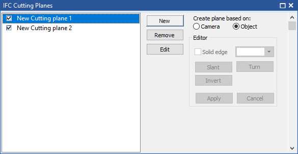
This pane displays a list of cutting planes that have been created for the 3D model or group model, and controls you can use to create new cutting planes, and to edit and delete existing cutting planes. To toggle the IFC Cutting Planes pane on and off, on the 4D tab, in the Panes group, click Cutting Planes.
You can create as many cutting planes as you want, but you can display only six at a time on a 3D model or IFC group model.
To create a cutting plane:
- On the IFC Cutting Planes pane, click the Camera or Object radio button to specify which type of cutting plane you want to create:
- Click Camera to create a 'camera-based' cutting plane, based on the current orientation of the camera.
 Illustration
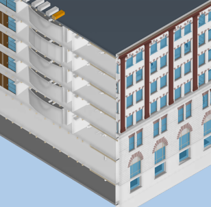
In the following illustration, the corner of part of a 3D model is displayed with no cutting planes, so all you can see is the exterior of the building:
In the following illustration, a cutting plane has been applied to the 3D model, based on the current orientation of the camera. This is a 'camera-based' cutting plane. As the cutting plane is based on the current camera orientation, it appears 'face-on' to you as soon as it has been applied. The cutting plane 'cuts off' the corner of the building, enabling you to view the interior:
In the following illustration, the camera angle has changed and a different 'camera-based' cutting plane has been applied to the 3D model. Because the camera angle has changed, the cutting plane cuts the building at a different angle:
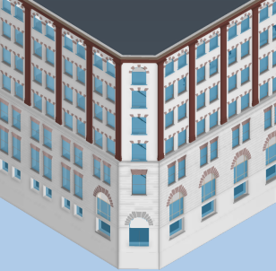
- Click Object to create an 'object-based' cutting plane, based on one side of a 3D object.Illustration
In the following illustration, the corner of part of a 3D model is displayed with no cutting planes, so all you can see is the exterior of the building:
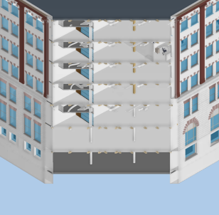
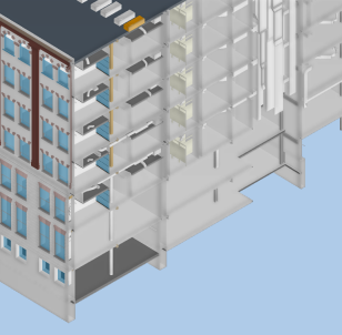
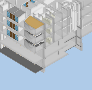
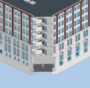
In the following illustration, a cutting plane has been applied to the 3D model, based on one side of a 3D object. This is an 'object-based' cutting plane. The cutting plane cuts through the building in a plane corresponding to the right-hand side of the selected 3D object - in this case, an object on the roof of the building:
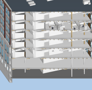
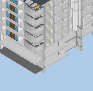
In the following illustration, a different 'object-based' cutting plane has been applied to the 3D model, this time based on a different side of the same 3D object. This cutting plane cuts through the building in a plane corresponding to the left-hand side of the 3D object on the roof:
- Click Camera to create a 'camera-based' cutting plane, based on the current orientation of the camera.
- Click New.
- Move the mouse pointer over the 3D model or IFC group model until the cursor appears like this:

- If you are creating a 'camera'-based' cutting plane, position the mouse pointer over the 3D model or IFC group model at the point at which you want to 'cut' the model; if you are creating an 'object-based' cutting plane, position the mouse pointer over the side of a 3D object that you want to use as the basis of a cutting plane.
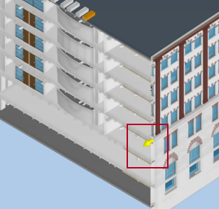
- Click the left mouse button. The cutting plane is applied to the 3D model or IFC group model. It appears with a yellow 'manipulator' arrow, which is positioned perpendicular to the cutting plane.You can now use the controls in the Editor group, on the IFC Cutting Planes pane, to configure the appearance of the cutting plane and to fine-tune its position. Refer to the following sections for details of how to do this.Illustration
A cutting plane with the yellow manipulator arrow highlighted is illustrated below:
- When you are happy with the appearance of the cutting plane, click Apply. The cutting plane is applied and the yellow manipulator arrow disappears, indicating that the cutting plane is no longer in edit mode. You can now apply further cutting planes to the 3D model or IFC group model if required.Illustration
You can apply more than one cutting plane to a 3D model at the same time. In the following illustration, two 'object-based' cutting planes have been applied to the 3D model, resulting in the building being cut open in two different planes at once:
In the following illustration, a third 'object-based' cutting plane has been applied to the 3D model. The third cutting plane effectively cuts off the top two storeys of the building, resulting in the building being cut open in three different planes at once:
By default, the edges of cutting planes - ie the points at which they cut across 3D objects - appear in white - they are not highlighted. You can choose to apply a different colour to the edge of a cutting plane, to make it more obvious. You can also apply a solid edge to cutting planes, which highlights even more strongly the points at which they cut across 3D objects.
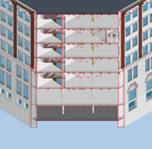
In the following illustration, a red edge has been applied to a cutting plane. The red edge highlights the points at which the cutting plane cuts across 3D objects:
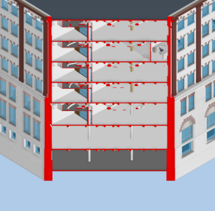
In the following illustration, a solid red edge has been applied to the cutting plane. The solid red edge 'fills in' the edges of 3D objects that are cut by the cutting plane, making the edge of the cutting plane more obvious:
To highlight the edge of a cutting plane:
- If you are editing an existing cutting plane, select the cutting plane in the list on the IFC Cutting Planes pane then click Edit. The cutting plane is put into edit mode, and a yellow manipulator arrow appears on the cutting plane:

You can only edit a cutting plane if it is currently turned on - displayed on the 3D model or IFC group model. If you have just created the cutting plane and have not yet clicked Apply - if the yellow manipulator arrow is already displayed against the cutting plane - there is no need to carry out this step, as the cutting plane is already in edit mode. - To apply a different colour to the edge of the cutting plane, click the colour selector and select the colour you want to apply.
- To apply a solid edge to the cutting plane, select the Solid edge check box; clear this check box to remove the solid edge from the cutting plane.
- Carry out any further edits to the appearance of the cutting plane, then click Apply.
If you apply a solid edge to a cutting plane then manipulate the cutting plane - either by pushing and pulling it backwards and forwards, slanting it around a horizontal axis or turning it around a vertical axis - the Solid edge check box is cleared and the solid edge is removed from the cutting plane. To reapply the solid edge to the cutting plane after manipulating it, reselect the Solid edge check box.
When a cutting plane is in edit mode - when its yellow manipulator arrow is displayed - you can push and pull it backwards and forwards, moving the cutting plane on the 3D model or IFC group model while retaining its orientation.
In the following illustration, a cutting plane has been applied to a 3D model:
In the following illustration, the cutting plane has been pushed backwards. In this case, this makes more of the interior of the 3D model visible:
In the following illustration, the cutting plane has been pulled forwards. In this case, this makes less of the interior of the 3D model visible:
To push and pull a cutting plane backwards and forwards:
- If you are editing an existing cutting plane, select the cutting plane in the list on the IFC Cutting Planes pane then click Edit. The cutting plane is put into edit mode, and a yellow manipulator arrow appears on the cutting plane:
You can only edit a cutting plane if it is currently turned on - displayed on the 3D model or IFC group model. If you have just created the cutting plane and have not yet clicked Apply - if the yellow manipulator arrow is already displayed against the cutting plane - there is no need to carry out this step, as the cutting plane is already in edit mode. - Move the mouse pointer over the 3D model or IFC group model until it is positioned directly over the yellow manipulator arrow:

- To push the cutting plane backwards, making more of the interior of the model visible, click and hold down the left mouse button while pushing the mouse away from you; to pull the cutting plane forwards, making less of the interior of the model visible, click and hold down the left mouse button while pulling the mouse towards you.
If the mouse pointer is not positioned directly over the yellow manipulator arrow, you will move the camera position in relation to the model, rather than pushing or pulling the cutting plane. - Release the left mouse button when you are happy with the position of the cutting plane.
- If you want to push or pull the cutting plane again, you can click and drag the yellow manipulator arrow as many times as you like to move the cutting plane to the required position.
- Carry out any further edits to the appearance of the cutting plane, then click Apply.
When a cutting plane is in edit mode - when its yellow manipulator arrow is displayed - you can slant it around a horizontal axis of your choice.
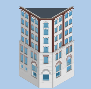
In the following illustration, a cutting plane has been applied to a 3D model:
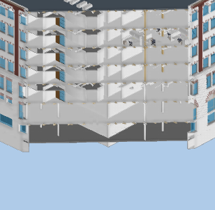
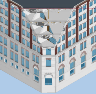
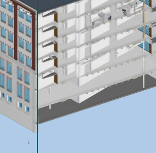
In the following illustration, the cutting plane has been slanted with a horizontal axis along the roofline of the building where it is cut by the cutting plane, with the lower edge slanted forwards. Although it is not obvious with the axis in this position, the upper edge of the cutting plane is slanted backwards. This makes the cutting plane cut through the building diagonally, revealing less of the lower floors. For illustration purposes only, the axis around which the cutting plane is slanted is indicated with a red line; this line does not appear in Asta Powerproject 4D:
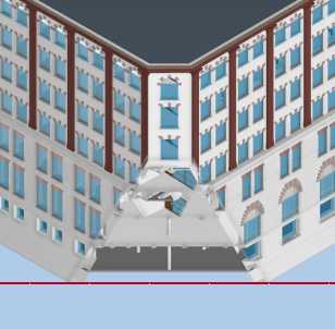
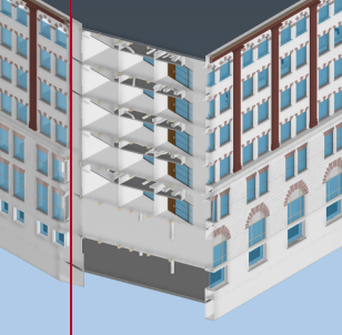
In the following illustration, the cutting plane has been slanted with a horizontal axis along the bottom edge of the building where it is cut by the cutting plane, with the upper edge slanted forwards. Although it is not obvious with the axis in this position, the lower edge of the cutting plane is slanted backwards. This makes the cutting plane cut through the building diagonally, revealing less of the upper floors. Again, the axis is indicated with a red line:
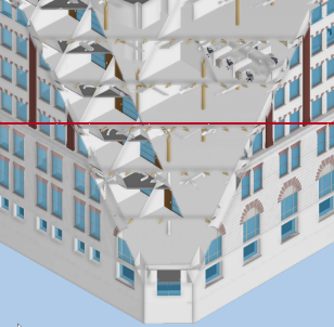
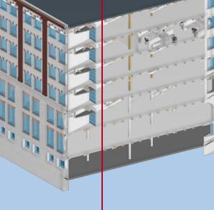
In the following illustration, the cutting plane has been slanted with a horizontal axis along the middle of the portion of the building that is cut by the cutting plane, with the lower edge slanted forwards and the upper edge slanted backwards. This makes the cutting plane cut through the building diagonally, revealing more of the upper floors and less of the lower floors. Again, the axis is indicated with a red line:
To slant a cutting plane around a horizontal axis:
- If you are editing an existing cutting plane, select the cutting plane in the list on the IFC Cutting Planes pane then click Edit. The cutting plane is put into edit mode, and a yellow manipulator arrow appears on the cutting plane:
You can only edit a cutting plane if it is currently turned on - displayed on the 3D model or IFC group model. If you have just created the cutting plane and have not yet clicked Apply - if the yellow manipulator arrow is already displayed against the cutting plane - there is no need to carry out this step, as the cutting plane is already in edit mode. - Click the Slant button in the IFC Cutting Planes pane.
- Move the mouse pointer over the 3D model or IFC group model at the level at which you want your horizontal axis to be. You do not need to position the mouse pointer over the yellow manipulator arrow. The cursor appears as a cross shape:

- To slant the lower edge of the cutting plane backwards and the upper edge forwards, click and hold down the left mouse button while pushing the mouse away from you; to slant the lower edge of the cutting plane forwards and the upper edge backwards, click and hold down the left mouse button while pulling the mouse towards you. A black circle appears at the point at which you click, showing the location of the axis:

- Release the left mouse button when you are happy with the position of the cutting plane.
- If you want to slant the cutting plane again, you must click the Slant button in the IFC Cutting Planes pane again before clicking and dragging: if you try to slant the cutting plane again without first clicking Slant, you will move the camera position in relation to the model, rather than slanting the cutting plane
- Carry out any further edits to the appearance of the cutting plane, then click Apply.
When a cutting plane is in edit mode - when its yellow manipulator arrow is displayed - you can turn it around a vertical axis of your choice.
In the following illustration, a cutting plane has been applied to a 3D model:
In the following illustration, the cutting plane has been turned anticlockwise, with a vertical axis along the left edge of the building where it is cut by the cutting plane. This makes the cutting plane cut through the building diagonally, revealing more of the building to the right of the axis. For illustration purposes only, the axis around which the cutting plane is turned is indicated with a red line; this line does not appear in Asta Powerproject 4D:
In the following illustration, the cutting plane has been turned clockwise, with a vertical axis along the left edge of the building where it is cut by the cutting plane. This makes the cutting plane cut through the building diagonally, revealing less of the building to the right of the axis. For illustration purposes only, the axis around which the cutting plane is turned is indicated with a red line; this line does not appear in Asta Powerproject 4D:
In the following illustration, the cutting plane has been turned anticlockwise, with a vertical axis along the middle of the portion of the building that is cut by the cutting plane. This makes the cutting plane cut through the building diagonally, revealing more of the building to the right of the axis and less of the building to the left of the axis. For illustration purposes only, the axis around which the cutting plane is turned is indicated with a red line; this line does not appear in Asta Powerproject 4D:
To turn a cutting plane around a vertical axis:
- If you are editing an existing cutting plane, select the cutting plane in the list on the IFC Cutting Planes pane then click Edit. The cutting plane is put into edit mode, and a yellow manipulator arrow appears on the cutting plane:
You can only edit a cutting plane if it is currently turned on - displayed on the 3D model or IFC group model. If you have just created the cutting plane and have not yet clicked Apply - if the yellow manipulator arrow is already displayed against the cutting plane - there is no need to carry out this step, as the cutting plane is already in edit mode. - Click the Turn button in the IFC Cutting Planes pane.
- Move the mouse pointer over the 3D model or IFC group model at the level at which you want your vertical axis to be. You do not need to position the mouse pointer over the yellow manipulator arrow. The cursor appears as a cross shape:
- To turn the cutting plane anticlockwise, click and hold down the left mouse button while moving the mouse to the right; to turn the cutting plane clockwise, click and hold down the left mouse button while moving the mouse to the left. A black circle appears at the point at which you click, showing the location of the axis:
- Release the left mouse button when you are happy with the position of the cutting plane.
- If you want to turn the cutting plane again, you must click the Turn button in the IFC Cutting Planes pane again before clicking and dragging: if you try to turn the cutting plane again without first clicking Turn, you will move the camera position in relation to the model, rather than turning the cutting plane
- Carry out any further edits to the appearance of the cutting plane, then click Apply.
When a cutting plane is in edit mode - when its yellow manipulator arrow is displayed - you can 'invert' it, which results in the portion of the 3D model on the opposite side of the cutting plane being visible.
In the following illustration, a cutting plane has been applied to a 3D model:
In the following illustration, the cutting plane has been inverted, so the portion of the 3D model that was previously hidden is visible, and the portion that was previously visible is hidden:
To invert a cutting plane:
- If you are editing an existing cutting plane, select the cutting plane in the list on the IFC Cutting Planes pane then click Edit. The cutting plane is put into edit mode, and a yellow manipulator arrow appears on the cutting plane:
You can only edit a cutting plane if it is currently turned on - displayed on the 3D model or IFC group model. If you have just created the cutting plane and have not yet clicked Apply - if the yellow manipulator arrow is already displayed against the cutting plane - there is no need to carry out this step, as the cutting plane is already in edit mode. - Click the Invert button in the IFC Cutting Planes pane.
- Carry out any further edits to the appearance of the cutting plane, then click Apply.
Once you have set up a cutting plane, you can turn it on and off, without having to delete it. As you can display a maximum of six cutting planes at any one time, if you have created more than six cutting planes for a 3D model or IFC group model, you specify which ones to display by turning the display of unwanted ones off.
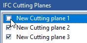
To turn a cutting plane off, preventing it from being displayed in the 3D model or IFC group model, clear the check box to the left of its name in the IFC Cutting Planes pane:
To redisplay a cutting plane, select the check box to the left of its name in the IFC Cutting Planes pane.
Each cutting plane is given a default name automatically when it is created. You can change the name of a cutting plane at any time. You might want to do this to give your cutting planes more descriptive names.
To change the name of a cutting plane:
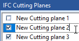
- Double-click the name of the cutting plane in the IFC Cutting Planes pane. A text insertion cursor appears in the cutting plane's name:
- Edit the name of the cutting plane, then either press ENTER or click away to save your changes.
You can delete cutting planes that are no longer required. Note that if you delete a cutting plane that was displayed when a snapshot was taken or when a fly past point was added, the deleted cutting plane will no longer appear in the snapshot or fly past.
To delete a cutting plane:
- Click the name of the cutting plane in the IFC Cutting Planes pane.
- Click Remove in the IFC Cutting Planes pane.
If you use the IFC Comparison Model pane to display an alternative view of a 3D model or IFC group model, you can choose whether or not to display cutting planes in the IFC Comparison Model pane. Displaying cutting planes in the IFC Model pane but omitting them from the IFC Comparison Model pane enables you to view a 3D model both with and without cutting planes at the same time.
To specify whether to display cutting panes in the IFC Comparison Model pane, right-click the IFC Comparison Model pane and select Show Cutting Planes from the menu that appears. This control is a toggle: each time you select it, cutting planes are either displayed or hidden in the IFC Comparison Model pane.
If you create one or more cutting planes in a multi-user project, the other users will only be able to see your cutting planes if they log into the project using your user name and password. If they log into the project using a different user name and password, your cutting planes will be absent.
"Walking through" the interior of a 3D model